VitaPCB is a reliable pcb manufacturer in China, any item you need, feel free to contact us.
🔶 Key Advantages of Gold Finger PCBs
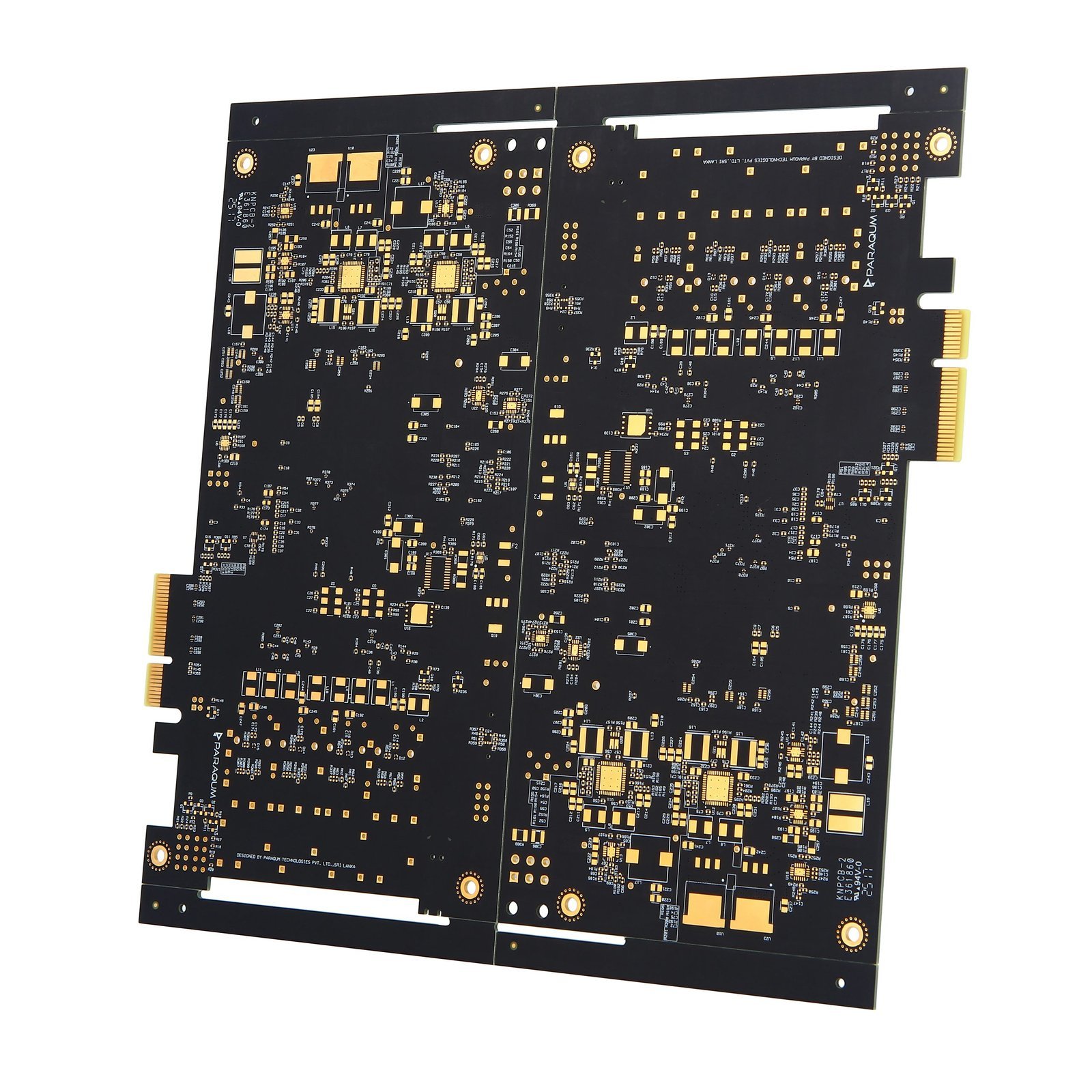
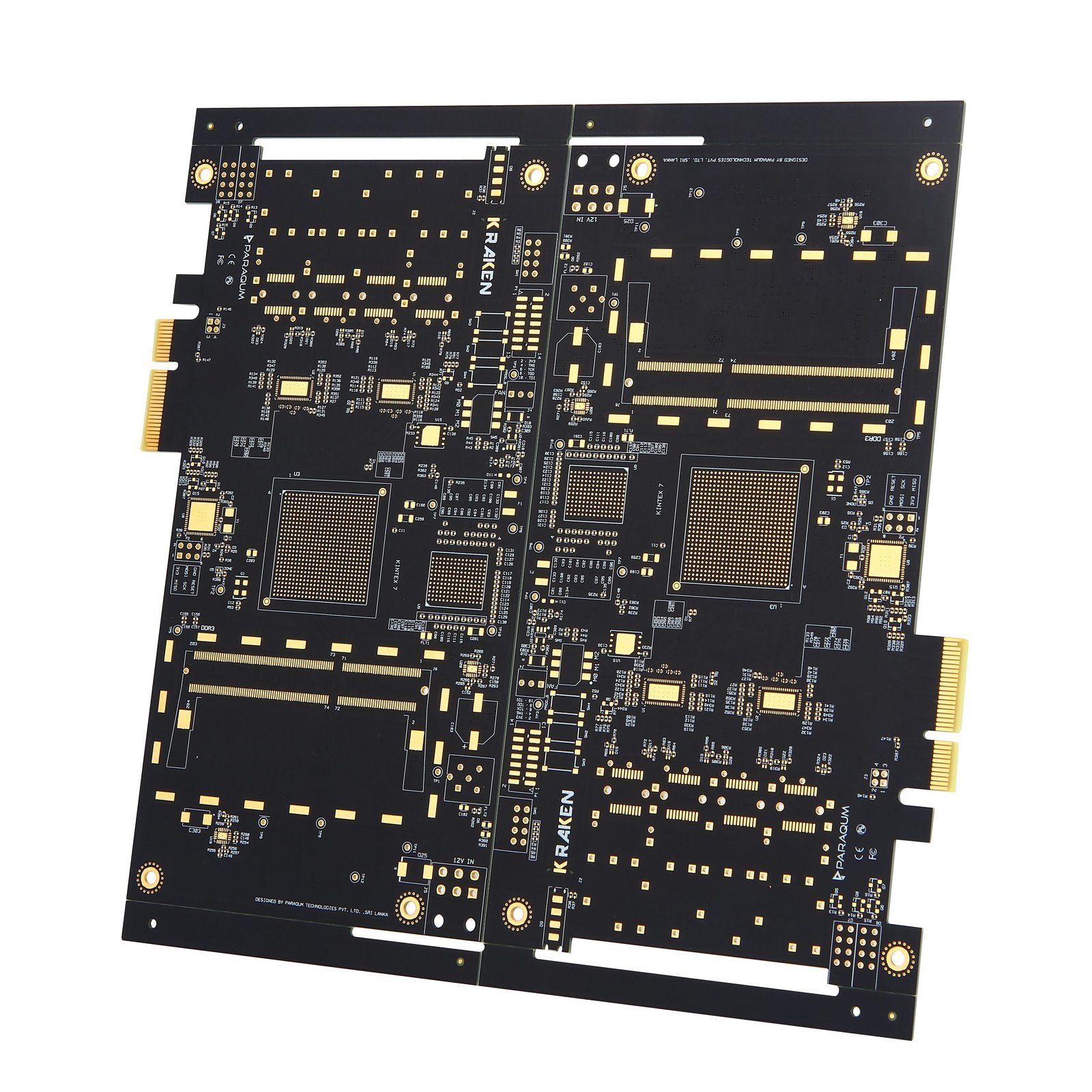
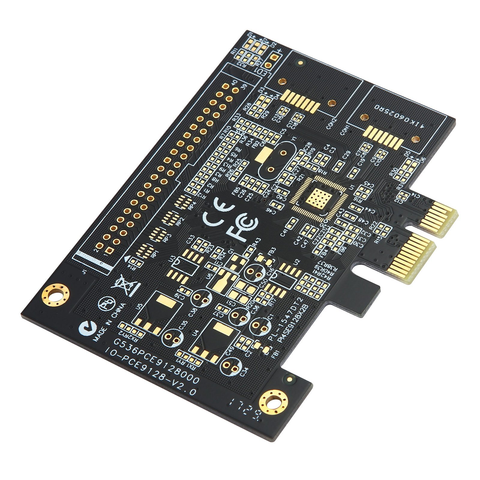
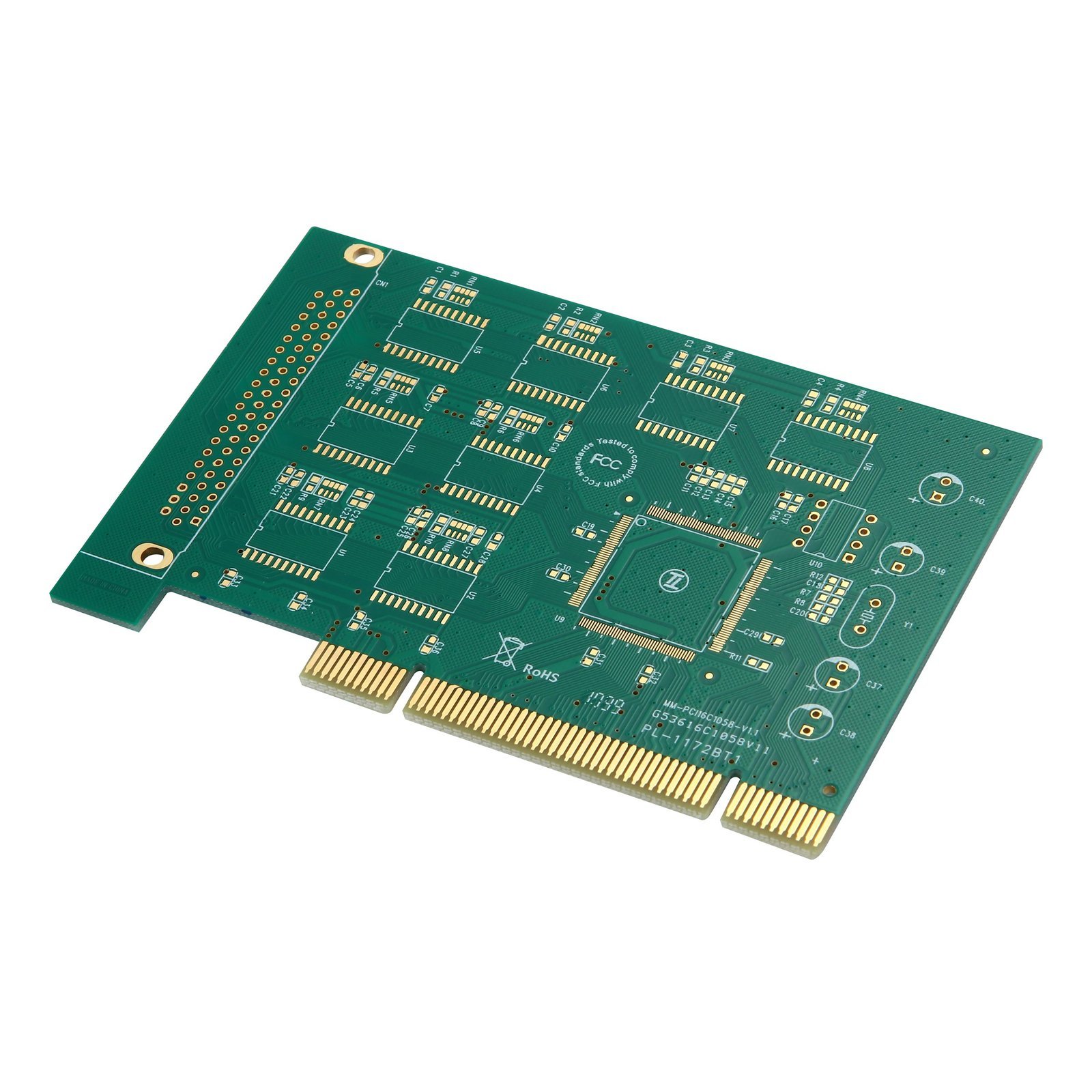
Gold Finger PCBs are specially designed circuit boards that feature edge connectors plated with hard gold. These edge connectors act as durable contact points for insertion into sockets, making them ideal for high-reliability, high-frequency insertion/removal operations.
🟨 Exceptional Durability & Wear Resistance
Gold fingers are plated with hard electrolytic gold (typically 10–50 μin), offering superior abrasion resistance and a long insertion lifespan—often exceeding 1,000 cycles without performance loss.
⚡ Low Electrical Contact Resistance
Gold is an excellent conductor with high oxidation resistance, ensuring stable, low-resistance connections even in harsh environments. This makes Gold Finger PCBs ideal for critical interconnects in high-speed data transfer systems.
🔁 Hot-Swap Friendly Design
With optimized beveling and chamfering, gold fingers allow for seamless hot-plug and hot-swap capabilities, commonly used in computer components, data servers, and industrial modules.
📐 Customizable Edge Configuration
Designers can tailor gold finger lengths, widths, chamfer angles (e.g., 30°, 45°), and spacing to fit application-specific socket or slot geometries, supporting edge-plug, backplane, and modular designs.
🌐 Wide Industry Adaptability
Whether used in telecommunications or military-grade systems, Gold Finger PCBs maintain excellent mechanical and electrical properties under frequent mechanical stress.
🔶 Applications of Gold Finger PCBs
Gold Finger PCBs are the go-to solution for components requiring frequent plugging, reliable edge-connection, and minimal signal loss.
● Computing & Data Systems
• Graphics cards (GPU)
• RAM modules
• PCIe cards
• Solid-State Drives (SSDs)
● Telecommunications Equipment
• Baseband units
• High-speed interface modules
• Backplane & daughterboards
● Industrial & Automation
• Control system modules
• PLC boards
• Testing & diagnostic cards
● Aerospace & Military
• Plug-in radar modules
• Satellite interface cards
• Rugged field units
🔶 Technical Specifications
| Layer Count | 2 – 20 layers, supporting simple to mid-complex edge-connector modules |
| Material | FR4, High-Tg FR4, Polyimide – offering mechanical durability and thermal stability |
| Board Thickness | 0.8 mm – 3.2 mm, compatible with most edge-slot socket designs |
| Gold Finger Plating | Hard gold (10–50 μin Au over 100–200 μin Ni), ensuring excellent wear resistance |
| Bevel Angle | 30°, 45°, or customized, for smooth insertion and reliable contact |
| Edge Connector Pitch | Min. 0.6 mm, adaptable to high-density edge configurations |
| Min. Line Width / Spacing (LW/LS) | 0.075 mm / 0.075 mm (3 mil), enabling high-density signal routing |
| Min. Drill Size | 0.2 mm (mechanical), suitable for standard and microvia integration |
| Impedance Control | ±10% tolerance on differential and single-ended lines, ideal for high-speed I/O |
| Surface Finish | ENIG, Hard Gold (Selective), Immersion Silver – based on application needs |